
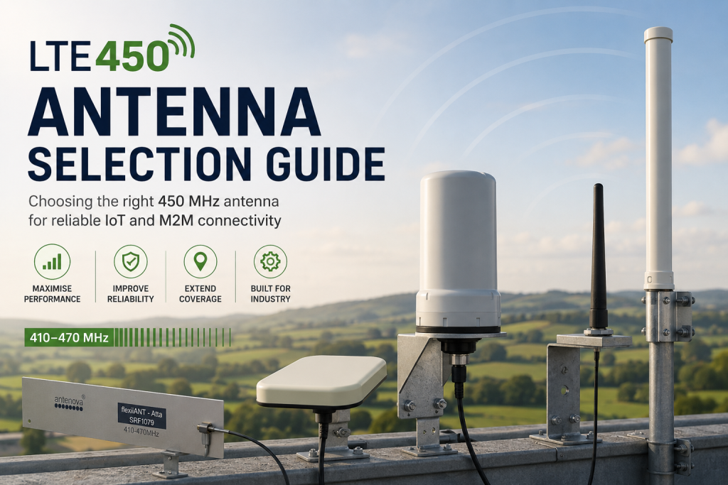
When deploying cellular networks for critical national infrastructure (CNI), smart grids, and smart metering, physical space and geography are your greatest enemies. High-frequency consumer bands (like 1.8 GHz, 2.1 GHz, or the mid-band 3.5 GHz 5G spectrum) rely on short paths and high line-of-sight density. If an asset is buried in a concrete basement or located deep in a rural forest, high frequencies struggle to make the connection.
This is why LTE450 (operating across 3GPP Bands 31, 72, 87, and 88) has emerged as the premier choice for utility operators. Its sub-1 GHz frequency offers incredible building penetration and massive geographic range.
However, these low-frequency physical advantages come with a significant catch: antenna physics.
In this comprehensive guide, we will analyze the relationship between 450 MHz propagation and physical antenna design, explore how sub-1 GHz signals overcome harsh environments, and break down four distinct, high-performance LTE450 antennas currently shaping the industrial IoT ecosystem.
1. The Physics of 450 MHz: Propagation, Penetration, and Wave Behavior
To understand why selecting a specialized antenna is critical for LTE450, we have to look at the relationship between frequency, wavelength, and signal propagation.
In wireless communication, the physical size of an antenna element is directly bound to the wavelength (λ) of the frequency it is designed to receive. This relationship is defined by the standard wave equation:
λ = v / f
Where v is the velocity of electromagnetic waves (the speed of light, 3 × 10^8 m/s) and f is the frequency in Hertz.
- At 2100 MHz (2.1 GHz), a standard commercial 4G frequency, the wavelength is roughly 14.2 cm. A standard quarter-wave monopole antenna is a mere 3.5 cm long.
- At 450 MHz, the wavelength expands to 66.6 cm. A quarter-wave antenna element must be approximately 16.6 cm long.
What This Wavelength Means for Signal Behavior
While a 66.6 cm wavelength requires physically larger antennas, it provides physical properties that high-frequency signals cannot replicate:
- Diffraction Over Terrain: Electromagnetic waves diffract (bend) around obstacles that are smaller than, or comparable to, their wavelength. A 66 cm wave easily bends around hills, dense foliage, and large industrial structures, keeping remote rural sites connected.
- Deep Building and Basement Penetration: High-frequency waves are easily absorbed or reflected by thick brickwork, reinforced concrete, and asphalt. Lower frequencies travel through these materials with much lower path loss, allowing signals to reach smart meters in deep basements, subterranean water valves, and indoor substations.
- Fewer Base Stations: Because path loss in free space increases exponentially as frequency rises, an LTE450 base station can cover an area up to 10 times larger than a standard 1.8 GHz cell site. This significantly reduces the network operator’s infrastructure footprint.
2. Key Engineering Properties of LTE450 Antennas
Designing a high-performance antenna for 450 MHz is a balancing act between size, mechanical stability, and RF performance. When auditing hardware, engineers must pay close attention to three core properties:
Impedance Matching and VSWR
An antenna must transform the electrical energy from the coax cable into electromagnetic waves in the air. This requires precise impedance matching (typically to 50 ohms). If the matching is poor, a portion of the transmitted energy is reflected back down the cable toward the router.
This reflection is measured as VSWR (Voltage Standing Wave Ratio). A perfect match is 1:1, while a VSWR under 2:1 is considered excellent for industrial applications.
Ground Plane Dependency
Many standard antennas rely on a “ground plane”—a metallic surface (like a vehicle’s steel roof or a metal cabinet) that acts as the second half of the dipole element.
- Ground-Plane Dependent: If mounted on a plastic enclosure or a wood pole, these antennas suffer from severely degraded gain, shifted resonant frequencies, and poor VSWR.
- Ground-Plane Independent: Highly engineered LTE450 antennas are built to operate without a ground plane, making them suitable for fiberglass kiosks, wooden utility poles, and remote masonry walls.
MIMO (Multiple-Input, Multiple-Output)
LTE systems rely on MIMO technology, using multiple antennas to transmit and receive data streams simultaneously over the same frequency. At 450 MHz, placing two antennas in close proximity can cause them to interfere with each other, hurting performance.
Integrating dual-MIMO elements into a single low-profile housing requires advanced isolators and clever spatial positioning inside the dome.
3. Four Specialized LTE450 Antennas Shaping the CNI Market
As the LTE450 ecosystem matures, top antenna manufacturers are developing innovative ways to pack 450 MHz elements into compact, rugged, and high-gain form factors. Let’s look at four distinct hardware options that meet these challenges.
A. Antenova Atta (SR4G077): The Embedded Flexible Solution
- Form Factor: Flexible Printed Circuit (FPC) Internal Antenna
- Key Stat: Ground-plane independent FPC measuring 101.0 mm × 20.0 mm × 0.15 mm
The Antenova Atta is a unique, high-efficiency flexible antenna designed to be integrated directly inside compact industrial enclosures, such as smart electricity, gas, or water meters.
Unlike traditional rigid whip antennas, the Atta is a “peel-and-stick” component that adheres directly to the inside wall of a plastic device housing. It operates independently of a ground plane, meaning its performance does not degrade when stuck to non-metallic enclosures. This makes it a great fit for space-constrained, sealed devices where exposing an external whip antenna would invite vandalism or environmental damage.
B. Panorama Antennas LTE 450MHz Range: Tough External Versatility
- Form Factor: Low-Profile Puck, Panel Mount, and Heavy-Duty Transit Antennas
- Key Stat: High integration combining 450 MHz LTE alongside multi-band 4G/5G, Wi-Fi, and GPS
As explored in our deep dive on Panorama Antennas and Robustel joining the 450 MHz Alliance, Panorama is a pioneer in robust, high-performance sub-1 GHz antenna engineering.
Panorama offers a wide range of ruggedized external antennas optimized for utility substations, smart grids, and transport networks. Their vehicular and cabinet-mounted puck antennas are housed in robust, heavy-duty, impact-resistant radomes designed to survive vandalism and extreme environmental exposure.
For multi-technology setups, Panorama provides combined antennas that house a dedicated 410-470 MHz element alongside wider 4G/5G, Wi-Fi, and GPS elements in a single panel-mount footprint, simplifying field installations.
C. Proscan Minimag-450: The High-Mobility Magnetic Mount
- Form Factor: Compact Magnetic Mount Whip Antenna
- Key Stat: Heavy-duty magnetic base with optimized quarter-wave steel whip
The Proscan Minimag-450 is designed for temporary deployments, fleet vehicles, rapid testing, and field diagnostics. It features a heavy-duty magnetic base that clings securely to steel vehicle roofs or metallic outdoor cabinets.
Because it uses the metal mounting surface as a ground plane, the Minimag-450 delivers highly efficient performance with a minimal physical footprint. The steel whip element is physically optimized to withstand wind resistance on moving vehicles while maintaining a stable radiation pattern at 450 MHz. It is a highly practical choice for field engineers who need to quickly connect an LTE450 diagnostic router on-site.
D. EAD LMO4547: The High-Gain Outdoor MIMO Workhorse
- Form Factor: Wall/Pole-Mounted MIMO Omnidirectional Antenna
- Key Stat: Dual-element MIMO covering both 450 MHz and wider 700-2700 MHz bands
When connecting remote substations or wind turbines that are miles away from the nearest base station, you need an external antenna with real high-gain performance. The EAD LMO4547 is a heavy-duty, wall- or pole-mounted omnidirectional MIMO antenna specifically built for permanent outdoor installations.
Housed in a durable, UV-stabilized white radome, the LMO4547 contains two separate, cross-polarized antenna elements. This dual-MIMO integration allows industrial routers (like those from Robustel) to maximize their uplink and downlink throughput over LTE450 Band 31 and Band 72.
Because it is fully omnidirectional, field technicians do not have to spend time precisely aligning it with a distant tower, reducing deployment times and installation costs.
4. LTE450 Antenna Selection: A Quick-Reference Matrix
To help you choose the right hardware for your deployment, this quick-reference matrix matches application requirements with the best antenna form factor:
| Deployment Scenario | Critical Requirement | Recommended Antenna Style | Example Hardware |
| Subterranean Water Meters | Water-tight seal, internal mounting, vandal resistance. | Internal FPC / Flexible Peel-and-Stick | Antenova Atta |
| Substation Kiosks / EV Chargers | Vandal-proof, weather-sealed, multi-frequency support. | Low-Profile Heavy-Duty Puck | Panorama low-profile range |
| Remote Rural Wind Farms | Maximum range, permanent outdoor pole mount, MIMO throughput. | High-Gain Omnidirectional MIMO Mast | EAD LMO4547 |
| Field Diagnostic Vehicles | Temporary mounting, rapid deployment, magnetic adhesion. | Magnetic Mount Whip | Proscan Minimag-450 |
To keep readers engaged on your site and avoid directing them away, let’s transform this final “Related LTE450 Topics” bulleted list into an on-page Technical Reference Hub and FAQ.
Pasting this directly into Gutenberg will build out a rich, scannable, and highly informative section that builds your site’s topical authority natively.
Related LTE450 Topics: On-Page Reference Hub
If you are researching, designing, or deploying sub-1 GHz cellular systems, use this on-page technical summary to answer key deployment questions immediately.
What is LTE450 and why does 450 MHz matter?
- The Core Concept: LTE450 is standard 4G LTE or 5G New Radio (NR) protocol running within the licensed spectrum between 410 MHz and 470 MHz.
- The Value Metric: Standard consumer cellular networks operate on higher bands (1.8 GHz to 3.5 GHz) to maximize data bandwidth at the cost of range. By dropping down to 450 MHz, the signal gains massive physical range and structural penetration properties, making it the ideal choice for utilities and Critical National Infrastructure (CNI).
Understanding propagation at 450 MHz
- Diffraction: The longer wavelength of a 450 MHz wave (approximately 66 cm) allows the signal to bend around large terrain obstacles, dense foliage, and heavy industrial buildings.
- Material Penetration: Lower frequency signals suffer significantly less signal attenuation when passing through wet concrete, brick, asphalt, and earth. This physical advantage allows LTE450 to establish stable links with smart meters in deep basements or underground chambers where standard 4G fails completely.
LTE450 routers explained
Unlike consumer-grade hardware, an industrial LTE450 router is built to serve as a secure edge computing node in harsh, unconditioned environments:
- Hardware Hardening: Encased in metal enclosures (IP30 rated or higher) and certified to operate under extreme temperature swings from $-40^\circ\text{C}$ to $+75^\circ\text{C}$.
- Legacy Interface Support: Features native RS-232 and RS-485 serial connections to communicate with legacy substation RTUs and PLCs, converting old Modbus or DNP3 serial protocols into secure IP-based traffic.
- Redundancy: Supports dual-SIM or eSIM failover architecture, keeping remote infrastructure connected by switching carriers if the primary network path drops.
Public vs. Private LTE450 networks
When architecting an LTE450 network, utility operators generally choose between two deployment models:
- The Private Model: The utility owns the dedicated spectrum and builds out its own private base stations (eNodeBs) and core network. This provides maximum control, zero monthly subscription fees, and absolute security isolation, though it demands higher upfront capital investment (CapEx).
- The Sourced/Shared Model: The utility leases secure network “slices” with strict Quality of Service (QoS) guarantees from a dedicated national CNI network operator (such as 450Connect in Germany). This accelerates deployment times and lowers CapEx while retaining the benefits of dedicated, non-congested spectrum.
Future of LTE450 and 5G RedCap
- 5G NR Integration: The 450 MHz band is fully standardized in 3GPP Release 17 and Release 18 specifications for 5G, ensuring decades of long-term support.
- 5G RedCap (Reduced Capability): RedCap introduces a highly efficient mid-tier device category designed to replace older LTE modems. It cuts power consumption, reduces device cost, and maintains high reliability over 450 MHz—allowing utilities to deploy millions of smart grid and smart metering endpoints directly onto 5G.